|
Sony EL-7
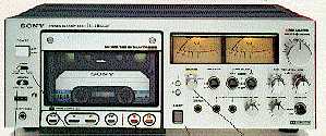
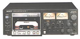
The Sony EL-7 was Sony's top of the line model. It retailed for US$880.
It appears that the EL-7 came in both silver and
black. Based on the units I have seen, the silver was apparently much more
common.
 
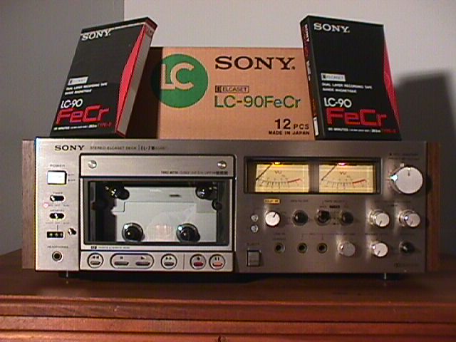
Some units came with wood side panels (actually they are particle board
with a vinyl wood-grain laminate). The wood panels are removable and are
interchangeable among any Sony Elcaset unit (EL-4, EL-5 or EL-7). Since
the wood panels are more prone to visible damage than the metal parts of the
unit, removing them can, in some cases, make the unit look better.
Just remove the two screws from each side of the unit, slide the panels back
about 2 centimeters, and then pull them away from the sides.
However, you must be careful if you want to do this. The side screws used
in the units with the panels are longer than those used on units without, and
replacing the long screws after removing the panels can severely damage the
unit. So be sure to shorten the screws before replacing them.

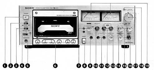
LOCATION AND FUNCTION OF CONTROLS
(From the EL-7 Owner's Manual, pages 4-5)
|
Note: This picture is an image map. Click on
one of the controls, or the corresponding number on the image, and you will be
taken to the description of that control. |

(1) POWER switch
This turns the power on or off. The VU meters will light when the unit is turned
on.
(2) TIMER switch
This permits automatic recording or playback at any desired time by using a
commercially available timer. For recording, set the switch to the REC position
(the red lamp will light up); for playback, set the switch to the PLAY position.
Be sure to set the switch to the OFF position when the timer is not used.
Otherwise, with the TIMER switch set at REC position, the previously recorded
material will be erased if the power is turned on.
(3) MEMORY switch
When the cassette is rewound to "000" of the tape counter (actually
"999" in order to avoid cutting off the starting point of the tape),
the tape motion stops from rewind mode with the switch set at STOP position, or
will replay from rewind with the switch set at START position.
(4) TAPE counter and reset button
At the start of recording, depress the reset button (000). The figures on the
tape counter change as the tape passes. Note the counter number for later
reference.
(5) HEADPHONES jack
This jack accepts 8 - 32 ohm headphones to monitor the input signals being
recorded, or to listen to playback of recorded material. The volume can be
adjusted with the PHONES LEVEL control.
(6) FUNCTION buttons
Rewind button--Depress this button for rewinding the tape.
Stop button--To stop the tape motion, depress this button. When a tape is fully
wound in any operating mode, the motor will stop automatically.
Forward button--Depress this button for playing back the tape. For recording,
depress this button and the red button simultaneously.
Fast-forward button--Depress this button for fast winding of the tape.
Record button--To start recording, depress this button and the red button
simultaneously.
Pause button--To momentarily pause during recording or playback, depress this
button. To restart, depress it again. Also, use this button for smooth start of
recording. (See "Recording" on page 8.)
(7)DOLBY NR switch*
FM: Use this position only when recording Dolby encoded FM broadcasts. For
playback, set the switch to the ON position. (See "Recording Dolby encoded
FM broadcasts" on page 10.)
ON: For recording and playback with Dolby NR process.
OFF: For non-Dolby NR processed recording and playback.
CAL: At this position, a fixed 400 Hz calibration tone is produced by the
oscillator. While recording this tone, the tape sensitivity can be adjusted by
setting the CAL controls so that the VU meters read "O (CAL)".
*"Dolby" and the double-D symbol are trademarks of Dolby Laboratories
Inc. Noise reduction system manufactured under license from Dolby Laboratories
Inc.
(8) EJECT button
Depress this button to open the cassette holder lid. It cannot be depressed when
the tape is in any operating mode.
(9) LINE IN (STEREO) jack
Use this stereo binaural jack as an auxiliary input for recording from another
tape recorder or tuner, etc. If the LINE IN jacks on the rear panel are engaged
at the same time, you can only record through this jack.
(10) MPX FILTER switch
Set this switch to the ON position only when recording FM stereo programs with
Dolby NR process and Dolby encoded FM programs. When recording other programs,
set the switch to the OFF position. This switch is inoperative in playback mode.
(11) MIC jacks
Any high-quality low-impedance microphone equipped with a phone plug may be
used. If your microphone is equipped with a mini plug, a plug adapter for
converting to phone plug is required.
(12) TAPE SELECT switches
On recording, set the EQ (for the correct equalization characteristics) and BIAS
(for the optimum bias current) switches correctly according to the type of tape
to be used. The type is indicated on the label of the ELCASET. The switches have
no effect upon the playback.
TYPE I for Sony SLH tape
TYPE II for Sony FeCr tape
TYPE III for CrO2 type of tape
(13) MIC ATT (attenuation) switch
This switch is useful for recording a large input signal on location (rock
music, etc.) or when recording with a microphone close to the source without
overloading recorder amplifier. It also eliminates having to set the REC LEVEL
and REC MASTER controls too far downward. Set the switch to "l5" or
"30" when the pointers of the VU meters swing repeatedly over the 0 VU
position even if the REC LEVEL and REC MASTER controls are set at a low level
position. At "15" position, the input level is attenuated by one fifth
(15 dB), and at "30" position, by one-thirtieth (3O dB).
(14) PHONES LEVEL control
This control adjusts the output level of headphones. At "O" position,
the sound can be heard slightly.
(15) REC LEVEL controls
These controls adjust the record level. The inner knob is for the right channel
and the outer for the left channel. The MIC controls adjust the record level
from the microphones. The LINE controls adjust the level from the LINE IN jacks
on either the front or rear panel. When the REC MASTER control is set at
"O" position, the input signal is completely reduced, and the record
level cannot be adjusted with MIC or LINE controls.
(16) MONITOR selector
For playback, set the selector to TAPE, and for record level adjustment, set it
to SOURCE.
(17) REC MASTER control and PRESET knob
This control adjusts the record level of both right and left channels
simultaneously. When the REC LEVEL controls are set at "O" position,
the input signal is completely reduced, and the record level cannot be adjusted
with this control.
(18) RECORD indicating lamp
This lamp will illuminate when the recorder is engaged in record mode.
(19) VU meters
With the MONITOR selector set to SOURCE, the meters indicate the input level
while recording. When set to the TAPE position, the meters indicate recorded
level being played back or monitor the level while recording. For correct record
level setting, see "Record level adjustment" on page 8.
Specifications for the
Sony EL-7
(From the EL-7 Owner's Manual, page 14)
| Power requirements |
120 V ac, 60 Hz |
| Power consumption |
43W |
| Tape speed |
9.5 cm/s (3 3/4 ips) |
| Fast forward and rewind time |
Approx. 60 seconds (by LC-60) |
| Recording system |
4-track 2-channel stereo |
| Bias frequency |
160 kHz |
Signal-to-noise ratio
|
DOLBY NR OFF
with Type II ELCASET (FeCr)
62 dB at peak level
With Type I ELCASET (SLH)
59 dB at peak level
DOLBY NR ON
Improved by 5 dB at 1kHz, l0 dB above 5kHz |
| Total harmonic distortion |
0.8% |
Frequency response
|
DOLBY NR OFF
with Type II ELCASET (FeCr)
15 - 27,000 Hz
25 - 22,000 Hz ±3 dB
With Type I ELCASET (SLH)
15 - 25,000 Hz
25 - 20,000 Hz ±3 dB |
| Wow and flutter |
0.04% WRMS |
| Inputs |
Microphone inputs (phone jacks) =
2
sensitivity 0. 3 mV (- 68 dB) for low impedance microphone
Line inputs (stereo binaural jack) = 1, (phono jacks) = 2
sensitivity 0.095V (-18dB) input impedance 100k ohms |
| Outputs |
Line outputs (phono jacks) = 2
output level 0.775V (OdB) at load impedance 100kohms with LEVEL ADJUST control
turned fully clockwise. Suitable load impedance more than 10k ohms.
Headphone output 1 suitable load impedance 8-32 ohms |
| Dimensions |
Approx. 460 x 170 x 320 mm
(w/h/d) (18-1/8 x 6-3/4X 12-5/8 inches) Including projecting parts and controls |
| Weight |
Approx. 13.5 kg (29 lbs. 13 oz) |
| Supplied accessories |
Connecting cord RK-74H (2)
Tape winder rod (1)
Head cleaning tips (1 set) |
PRECAUTIONS
(From the EL-7 Owner's Manual, page 3)
On safety
- Before operating, be sure the operating voltage of your unit is identical
with that of your local power supply.
- Should any liquid or solid object fall into the cabinet, unplug the unit and
have it checked by qualified personnel before operating it any further.
- Unplug the unit from the wall outlet if it is not to be used for an extended
period of time. To disconnect the cord, pull it out by the plug.
Never pull the cord itself.
On installation
- Good air circulation is essential to prevent internal heat buildup in the
unit. Place the unit in a location with adequate air circulation.
- Do not install the unit in a location near heat sources such as radiators or
air ducts, or in a place subject to direct sunlight, excessive dust or
mechanical vibration.
- The tape deck is designed for vertical operation only.
On head cleaning
The best performance of your tape deck depends on your periodic cleaning of
the heads and all surfaces over which the tape travels. Dirty heads and
tape path cause:
- Loss of high frequency response
- Loss of sound volume
- Sound drop-out, etc.
Cleaning should be done after every 10 hours of operation. For details,
see "Maintenance" on page 12.
On ELCASET
- Before inserting the ELCASET, use the supplied tape driver and take up the
slack of the tape to prevent it from becoming entangled around the capstan.
- Hold the ELCASET and face the tape surface up when inserting it in the tape
deck. Avoid touching the tape surface or pulling it out of the tape
housing.
For more information on the ELCASET, see pages 13 and 14.
Other important points to remember
- Before depressing the POWER switch, check to see that the TIMER switch is
set at off. This switch should only be placed to REC or PLAY for
timer-activated operation.
- Gently close the lid of the ELCASET holder to its locked position to protect
the tape from damage.
- The EJECT button cannot be depressed while the tape is in operating mode.
- Turn down the REC LEVEL controls not being used while recording.
- Never misplace the DOLBY NR switch. Place it to CAL only for
Calibration Level adjustments and to ON or OFF for Dolby or non-Dolby NR
recording.
CONNECTIONS
(From the EL-7 Owner's Manual, pages 6-7)
- Be sure the amplifier is turned off while making connections.
- Insert the plugs completely into jacks. Loose connections may cause
hum and noise.
- The red plug of the supplied connecting cord should be connected to the
right channel and gray plug to the left channel
LEVEL ADJUST control
The output level of the tape deck phono jacks can be set to correspond
accurately to the output level of other sources connected to the
amplifier. We recommend that you use either FM or Phono mode as a
reference point. While adjusting, do not change the volume control of the
amplifier. At the position turned fully clockwise, the output level is
rated 0.775 V (0 dB). The control does not correspond to the VU meters.
REMOTE CONTROL connector
Plug the Sony RM-30 Remote Control unit (optional) in this connector.
The RM-30 features "record muting"* as well as remote control
operation. Read the RM-30 instruction manual before operating it with the
tape deck.
* A device which is beneficial to short-circuit unwanted program
sources such as broadcasting commercials, thus allowing an interspace between
the recordings.
FM CAL controls
When recording Dolby encoded FM broadcasts, set the record level with these
controls. See "Recording Dolby encoded FM broadcasts" on page
10.
AC OUTLET
Use for the AC power supply of other audio components.
SWITCHED 200 W: AC power is supplied only when the tape deck POWER
switch is set to ON. Maximum consumption is 200W.
UNSWITCHED 300 W: This outlet is not controlled by the tape deck POWER
switch. Maximum consumption is 300 W.
MAINTENANCE
(From EL-7 Owner's Manual, page 12)
Cleaning of heads and tape path
Generally, cleaning after every 10 hours of operation will be
sufficient. However, all surfaces over which tape travels
TROUBLE CHECKS
(From the EL-7 Owner's Manual, page 16)
The following chart will help correct most problems which may occur with the
unit. If the problem persists after you have made these checks, consult
your nearest Superscope Service Centers.
Before going through the check list below, first pay attention to the
following fundamental points.
- The power cord must be connected firmly.
- Connection to the amplifier must also be firm.
- Heads, capstans and pinch rollers should be cleaned.
- The amplifier controls and switches should be set correctly.
FUNCTIONS BUTTONS AND TAPE PATH
The EJECT button cannot be depressed.
- This button is inoperative while tape is running or the PAUSE button is
depressed.
Tape does not move even when function buttons are depressed.
- The PAUSE button is depressed.
- The ELCASET holder is not closed fully
Recording of playback begins as soon as the POWER switch is ON.
- The TIMER switch is misplaced at either REC or PLAY.
Cassette hubs turn a bit after the POWER switch is ON.
- This is to remove tape slack when put in the tape deck.
Automatic shut-off mechanism does not work.
- The guide-pole lamp is dirty. (See "Maintenance" on page
12.)
Tape does not move after the POWER switch is ON, though the function
buttons are depressed.
- Push the desired function buttons approximately two seconds after the POSER
switch is ON. When less than this time interval is taken, logic-controlled
function buttons do not work.
RECORDING OR PLAYBACK
No recording or decrease of sound level.
- Erasure-proof tabs in the ELCASET are slid down. (See page 13.)
- Contamination of the heads. (See page 12.)
- The MIC ATT switch is set to either "15" or "30" when
recording from microphones.
Recording cannot be made from LINE IN jacks on the rear panel.
- The LINE IN jack (phone type) on the front panel is connected.
VU meters do not swing.
- The REC MASTER control of REC LEVEL controls are turned down to
"0".
Distorted sound.
- CAL level is too high. (See "Calibration level adjustment"
on page 10.)
- Recording level is too high.
Recording level drops when switching the MONITOR selector from SOURCE to
TAPE.
- CAL level is too low. (See "Calibration level adjustment" on
page 10.)
No playback or decrease of sound reproduction.
- The MONITOR selector is set at SOURCE.
- The LEVEL ADJUST control in the rear panel is turned down.
- Contamination of the heads. (See "Maintenance" on page 12.)
Too much wow or flutter, or drop-outs.
- Contamination of capstans or pinch rollers.
Insufficient erasure.
- Contamination of the erase head.
Increase of noise or erasure of high frequencies.
- Magnetic build-up on the heads.
Unbalanced tone in higher frequency range.
- The Dolby NR processed tape should be played back with the DOLBY NR switch
at the ON position, and the non-Dolby NR processed tape at the OFF position.
- The TAPE SELECT switches should be in the same position in both record and
playback modes. If recorded in the wrong position, adjust the tone on the
amplifier in playback.
Tape stops before the tape counter reads "000", though the
recorder is in memory counter operation.
- The tape counter is reset to "000" at the leader-tape
portion. (See "Memory counter operation" on page 11.)
Sound comes out a few seconds after the poser switch is ON.
- This occurs because muting circuit is provided to avoid any annoying
"thump" noise, and is not abnormal operation.
Recording sources cannot be monitored in the playback mode, when setting
the MONITOR selector to SOURCE.
- The Dolby NR switch is set at CAL position.
HOWLING OR HUM NOISE
Oscillation occurs when trying to record from the amplifier.
- If the LINE OUT jacks of the tape deck are connected to the amplifier AUX
jacks and these are switched on, change the amplifier input selector to another
position.
Oscillation occurs when trying to record from microphones.
- The microphone is too near the loud-speakers. Keep the microphone away
from them or reduce the amplifier volume.
Hum noise.
- The tape deck is stacked just on or below the amplifier.
|


